Locked by tidal forces, the Moon keeps one face toward Earth as it orbits, and its far side was never seen by man.
Program E2 was the next phase of Soviet Lunar exploration, proposed by Keldysh in January of 1958, it would photograph the far side of the Moon and transmit the images by television to Earth.
The Automatic Interplanetary Station
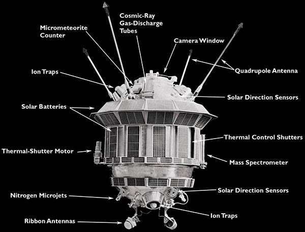
The E2A Automatic Interplanetary Station (Luna-3) In place of the E1 scientific pod, the E2 missions carried an "automatic interplanetary station" designed by Gleb Maximov. The probe was made from an aluminum alloy, cylindrical with hemispherical end caps. Weighing 278.5 kg, it was 130 cm long and 95 cm in diameter, with a wide section 120 cm in diameter. The hemispherical end caps are similar to the two halves of the E1 pod, with a noteable addition of a camera window on one end. Shutters protected the window glass from micrometeorite etching. Like the E1 pods, the probe was filled with nitrogen at 1.5 atm of pressure and had a ventilation fan to circulate the gas, carrying heat from equipment to the outer wall. In addition, a motor on the outside of the probe could slide shutters open or closed, to change the exposure of the wall to the cold of space. This system was designed to maintain an internal temperature of 25° C. Power was supplied by rechargable silver-zinc batteries, supplying 26 volts with a capacity of 6 amp-hours. Power usage varied. The 3-axis orientation system, for example, consumed 60 watts during its operation. Because of the long mission duration, the batteries were recharged by solar cells, installed by Nikolai Lidorenko. He had placed experimental solar cells on Sputnik-3, and like the American Vanguard satellite, they powered a radio beacon. However, Luna-3 was the first spacecraft with systems fully powered by solar cells.
Many of the E1 experiments were included on E2A, except for the magnetometer. The probe contained a Cherenkov detector, a NaI scintillation counter, three gas-discharge counters (some mounted externally), and four ion traps. Four micrometeorite counters were installed, smaller than the ones on E1 and having a total area of 0.1 square meters. Diagrams show a mass spectrometer mounted on the outside of the spacecraft, but it may have malfunctioned, since there are no results published from it. It was probably intended to test for any trace of a rarified Lunar atmosphere. In addition, Block-E contained 156.5 kg of scientific equipment. The probe sent data on two frequencies, 183.6 and 39.986 MHz, using the quadrupole antenna and a V-dipole ribbon antennas like to those on the E1 pods. The launched probe was designated E2A, because it had a new telemetry system, designed by Evgeny Boguslavsky at the Institute of Space Device Engineering (RNII KP). That system replaced the original E2 radio system, built by the Moscow Energy Institute. The Phototelevision System
To photograph the Moon, a phototelevision unit was developed at the Leningrad Scientific Research Institute of Television (NII-380), in an effort led by Petr Bratslavets. Work began in April 1958 on a system called Yenisey, designed to take photographs on film, automatically develop it, and then scan the images to generate a television signal. The flown camera was an improved version, which had two speeds of television scanning. The dual-objective optical component of the camera, code named AFA-E1, was build at the Krasnogorsk Mechanical Plant (KMZ), makers of cameras (both civilian and aerial reconnaissance), telescopes and other optical devices. It took two pictures simultaneously through a 200 mm lens with f/5.6 aperture and a 500 mm lens with f/9.5 aperture. To bracket exposure, the shutter speed cycled though 1/200, 1/400, 1/600 and 1/800 seconds.
After photography was complete, the film would be developed and fixed in a one-step chemical process. The film slid through rubber seals to enter and exit the chamber filled with the viscous reagent mixture. It was then dried and stored on a take-up reel. 40 frames of film were stored in the lead-lined magazine, each containing pre-exposed reference marks and photometric wedges for calibration purposes. These were preceded by a zebra-pattern (Shtrichovaya Mira) resolution chart and a standard 0249 television test chart. Following the 40 frames was a photograph of the Moon taken by telescope, the 0249 chart, and pre-developed copies of the 0249 and the zebra test charts. Once developed, the pictures could be scanned and transmitted repeated, upon radio command. During video transmission, a scanning spot of light from a model 8LK2B oscilloscope CRT was focused on the film, and the image was read by an FEU-15 photomultiplier tube. Images were scanned at about 1500 lines/frame at a rate of 0.8 lines/sec, or in a fast mode of 50 lines per second. The film was moved slowly and continuously during the scanning process. Video was sent on the 183.6 MHz carrier using 3 watts of power. The 400 Hz video signal was modulated by FM on a 25 kHz subcarrier. This gave an equivalent resolution of 1000 pixels per scan line. About 30 minutes were required to scan one frame. The Orientation System
The "Chaike" Orientation Control System
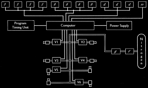
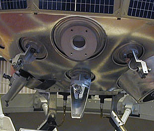
One of the most novel technologies in the E2 probe was the orientation control system, needed to aim its camera at the Moon. To solve this problem, Boris Raushenbakh and a team of engineers developed the first successful 3-axis stabilization system, called Chaike ("Seagull"). Wide-angle photocells measured the direction of the Sun, 4 around the camera window (S) and four on the aft (B). Three gyroscopes (d) measured angular velocity, and a narrow-angle Moonlight sensor (m) looked out through the window with five photocells. These fed into a special purpose computer built from relays, which in turn controlled 8 micro jets. Four jets aimed perpendicular to the central axis (Z) of the probe induced yaw and pitch. Two pairs of jets aimed at a tangent induced clockwise or counterclockwise roll. These could operate continuously, or for finer control, they could emit 1/10 second pulses. The jets were powered by a resevoir of nitrogen under 150 atm of pressure, reduced to 4 atm by a regulator (g).
During most of its mission, the probe would tumble slowly, initially with a period of 165 seconds. Before photography of the Moon, the orientation system would halt this motion, using feedback from the three angular-velocity sensors. All eight jets are needed to reduce rotation,= about all three axes to less than 0.15 deg/sec, which would take about 10 minutes. Next, the aft end of the probe must be pointed approximately toward the Sun, with a precision of about 5°. Only the four lateral jets, controlling yaw and pitch, are used for this operation, . In the plane perpendicular to the X axis, are four Solar sensors (two S and two B) and two jets. Based on sensor feedback, the jets act to maximize the S signals from the aft sensors and minimize the B signals. The same operation is performed independantly on the plane of the Y axis with the orthogonal set of four Solar sensors and two jets. Two of the gyroscopic rotation sensors (X and Y axes) are also employed to dampen motion. Given the launch date and trajectory, this would place the Moon within the 60° field of view of the Moonlight sensor (and the Earth was guaranteed to be well outside the view). Using the five-component sensor and the lateral jets, the camera was aimed at the Moon with a precision of 0.5°, a process that took about 30 minutes. After photography was complete, a small rotation (180 second period) was imparted to the craft before the orientation system shut down, so it would be heated evenly by the Sun during the rest of the mission. The gyroscopic angular-velocity sensors played a key role during these orientation maneuvers. In the absence of air friction, a spacecraft could oscillate forever, overshooting and correcting its aim. Raushenbakh�s system simulated the effect of friction by dampening the microjet impulses in proportion to angular velocity. Planning And Executing The Trajectory
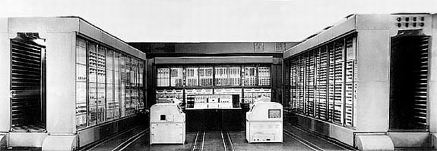
The Strela-1 Computer The trajectory of the E2 probe would be the most complex spacecraft maneuver performed up to then. To photograph the Moon from a distance of 40,000 to 100,000 km and return near the Earth for television transmission, the probe had to be launched on an orbit extending beyond the distance of the Moon. This in itself was a delicate operation, since the velocity after Block-E burn would have to be just 60-90 meters/sec below escape velocity. Soviet rockets and their tracking and guidance systems were designed to launch northward, but an orbit that traveled to the Moon from the north would return from the south, out of radio range of the Soviet Union's territory. The only solution was a gravity-assist maneuver, using the Moon to deflect the probe back in an orbit that returned from the north. The rocket would have to be aimed to pass near the Moon's south pole, coming within a few thousand kilometers of its surface. Dmitri Okhotsimsky oversaw this work, using the new Strela-1 computer at the Steklov Institute of Mathematics. Families of trajectories were calculated, simulating the gravitation attraction of the Earth, Moon and Sun. Considerations included launch energy, percentage of Lunar far side visible during photography and radio visibility from the USSR during the return flight and television transmissions. The study advised two radio reception points at the far eastern and western extremes of Soviet territory. Two photography times were considered: before closest approach, or afterwards while flying away from the Moon. Photographing the Earth was also considered but rejected.
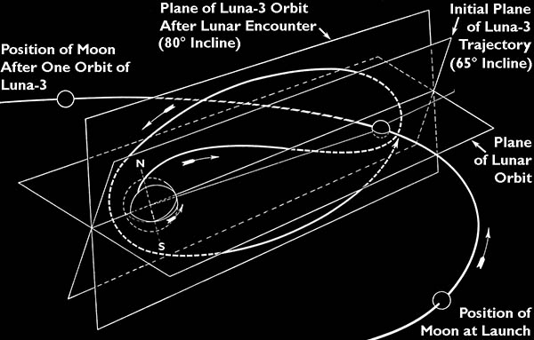
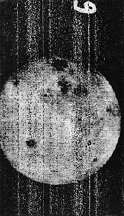
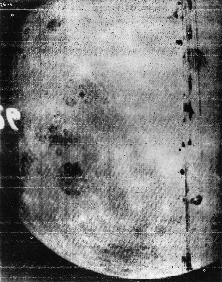
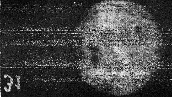
Luna-3 Trajectory The third Soviet cosmic rocket was launched on October 4, 1959 at 00:43:39.7 GMT. A few years later, it would retroactively become known as "Luna-3". October 4 was the second anniversary of Sputnik-1, and only two days before an optimum launch date calculated by Okhotsimsky. The probe reached its closest approach to the Moon (7940 km from center) at 14:16 GMT on October 6. At 03:30 October 7, at a distance of 65,200 km from the Moon, the program timing unit activated the phototelevision system. Photography lasted 40 minutes, ending at a distance of 68,400 km. At the midway point, the spacecraft position was λ=117.4°, β=17.1°, ρ=66,800 km in selenographic coordinates. The automatic chemical development of the film was then performed in about 15 minutes, completing the automatic cycle of the camera system. 17 images were acquired and relayed to Earth, although it is possible that 29 photographs were actually taken. 13 images of the Moon are known to exist, and several test patterns were probably also received. Receiving The ImagesVideo telemetry was received by two special radio stations, one at the Mount Kashka station in the Crimea and one at the telemetry station in Yelizovo on the Kamchatka peninsula. 8 hours was required to transmit the images, but the spacecraft's transmitter was operated for only one hour at a time, followed by two hours in standby mode, for solar recharging of batteries. Thus, a total of 25 hours was needed to download the entire set of images. Commands sent to the spacecraft initiated and controlled the film scanning and video transmission.
Two specialized video recording devices were built, Yenisey-I designed for recording of the video in fast mode (50 lines/sec) and Yenisey-II for slow mode (0.8 lines/sec). One of each device was installed in Simeiz and Yelizovo. The incoming video was recorded on several media. The FM video signal was recorded on magnetic tape, and images were stored on 35 mm film with a flying spot CRT. An electrochemical paper image was printed and a skiatron image storage tube was written, for immediate viewing. The Skiatron was also photographed for additional archiving of the valuable images. A skiatron tube records images by creating f-center dislocations in a crystalline screen, with an electron beam. The back-lit translucent screen becomes dark purple where exposed, and the image can be erased by heat. A simulation of the result is shown above.
Keldysh enlisted the help of British radio astronomer Bernard Lovell, who managed the massive radio telescope at Jodrell Bank. Lovell made some recordings of Luna-3 video, which he shared with the American Jet Propulsion Lab. They have not been seen, but are reported to only show a television test pattern. Sven Grahn has written an excellent history of the work at Jodrell Bank here and a history of the Luna-3 telemetry here.
The collection of images from Simeiz and Yelizovo, were sent to the Sternberg Astronomical institute, where Yuri Lipsky and his associates analyzed them extensively. Copies were also sent to the Pulkovo Observatory and the Gorky Observatory in Kharkov. The first results were published in Pravda on October 27, 1959, carefully reconstructed from the film recordings. Lipsky's team used equipment developed to create better images from the magnetic tape recordings of the video signal, and these were published in 1961 in Atlas Obratnoy Storony Luny. In 1967, a second volume of his atlas was published, with the new Zond-3 images, the second view of the Lunar far side. This also included an improved image made from the Luna-3 magnetic tape.
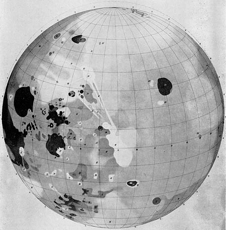
Pulkovo Observatory's Map The outstanding geological feature was the lack of large mare basins on the far side of the Moon. Teams at several institutes studied the photographs carefully to catalog and name details. The left crescent of Luna-3's view covers the front of the Moon, and about 70 percent of the far side of the Moon appeared on the right. The dark crator with the central peak in the south was named Tsiolkovsky and the large dark spot to the north Mare Muscoviense (Moscow Sea). Other craters were named after famous Russian scientists, such as Mendeleev, Lomonosov and even the atomic bomb scientist Kurchatov. Images from later spacecraft revealed a few mistakes, such as the Soviet Mountains, where turned out to be impact rays. After Luna-3, the far side of the Moon would not be seen again until Zond-3, in 1965. Complete coverage of the far side by photography was not complete until the American Lunar Orbiter 5, in August of 1967. The Luna-3 ImagesPublications indicate that frames 26 to 38 exist and contain images of the Moon. To date, only six of these have been published, in Lipsky's atlases. I continue to attempt to find more of these images, to be included in the collection that followes. A special thanks to Dr. Vladislav Shevchenko at the Sternberg Astronomical Institute for making scans of the original film recordings for me. Blank frames indicate images that I do not have yet:
Two types of test patterns were included on the Luna-3 film, a standard Soviet television chart and a type of zebra-stripe resolution chart called Shtrichovaya Mira. These are not actual images from Luna-3, they just illustrate what was imprinted on the film.
|
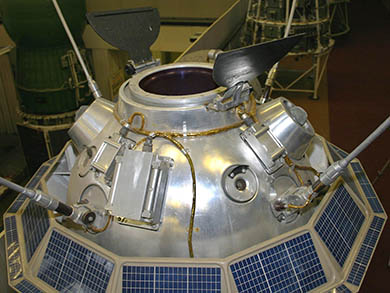 Sensors and Camera Window
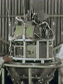 Equipment Framework
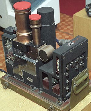 "Yenisey" Phototelevision System
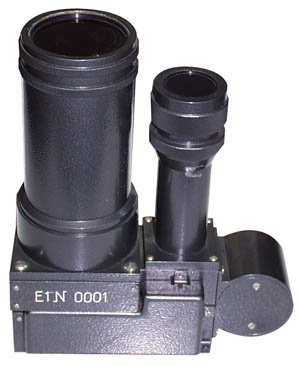 AFA-E1 Optical Component
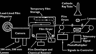 Diagram of Phototelevision System
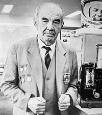 Petr Bratslavets
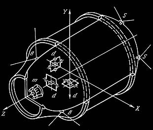 Sensors of Orientation System
 Micro Jets and a Solar Sensor
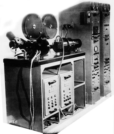 Yenisey-II Receiver
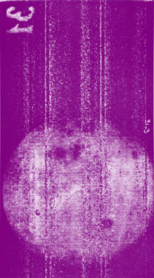 Skiatron Image (simulated)
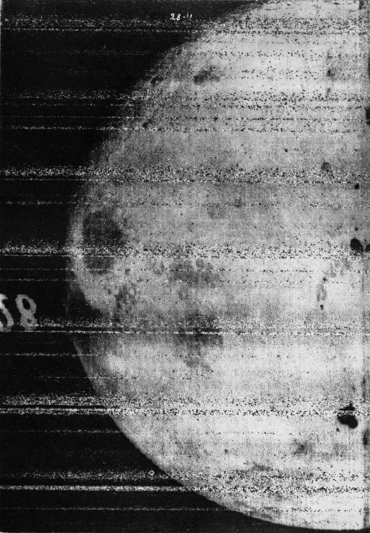
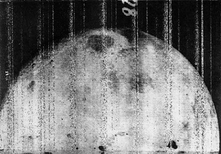 Frame 28 (500 mm lens)
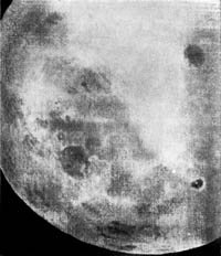
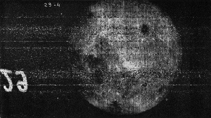
 Frame 29 (200 mm)
 Oct 27, 1959
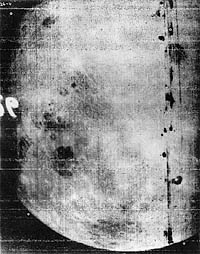 1961
1961
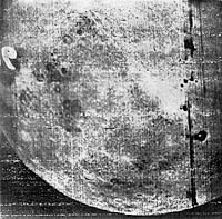 1967
1967


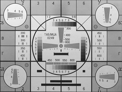 Television Test Card 0249
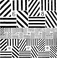 Shtrichovaya Mira