Russian radio technology has a long history, beginning with one of the early pioneers of wireless telegraphy, Alexander Popov, who demonstrated a working radio system in 1895.
In 1933, V.A. Kotel'nikov published the first rigorous formulation of the sampling theorem, pioneering modern communication theory.
In the 1950s, N.G. Basov and A.M. Prokhorov invented the MASER (independently with Townes of Columbia University), for which they shared in the Nobel Prize. This technology was an essential part of the ultra-sensitive receivers of deep-space communication systems.
Near-Earth Telemetry Systems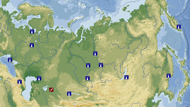
The first generation Russian space telemetry system, completed in 1957, was a set of 13 stations able to monitor rockets and satellites, from their launch point in Baikonur to the Kamchatka peninsula. Two additional facilities at Evpatoriia and Ussuriisk became the Western and Eastern Deep Space Communications Centers. Stations contained a number of optical and radio systems, including these systems built by the OKB-MEI bureau:
Missile-telemetry systems were modified in preparation for the highly complex scientific satellite Sputnik-3, codenamed Object-D. Modified systems were sometimes referred as Tral-D, Bambuk-D, etc. Similarly, the Vostok telemetry system was called Tral-K, and nuclear warhead test telemetry was Tral-G. |
 Luna-3
|
 The Far Side of the Moon
|
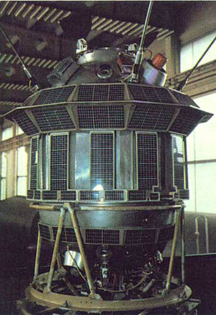
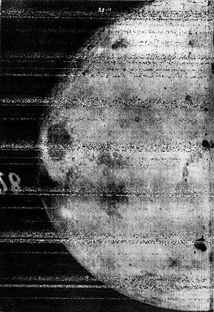
| The Object-E payloads were sent to the Moon, far beyond the range of the satellite telemetry system. Luna-3, in 1959, represented the greatest challenge, because it contained a camera. It took 29 photographs of the far side of the Moon on 35mm film, which was automatically developed, fixed, dried, and scanned at 1000 x 1000 pixel resolution. Images were transmitted as low-bandwidth FM video on 183.600 MHz. |
 Early Telemetry System
|
 Multiplexed PDM Signal
|
|
Luna probes used short-wave frequencies to send analog science data by pulse-duration modulation.
The famous
beeping
of Sputnik-1 was a PDM signal, encoding internal pressure as pulse length and temperature as length between pulses.
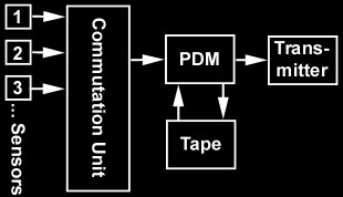
Later spacecrafts used multiplexed PDM, with a commutator that cycled different sensor outputs to the transmitter. A tape recorder might store the PDM subcarrier tones for later playback.
In addition to multiplexing, several transmitters could send data on multiple frequencies (e.g., 39.986 MHz, 19.993 MHz, 19.997 MHz, 20.003 MHz for Luna-3).
Both the probe and the rocket's final stage, which traveled on the same trajectory, might be used to house the mission's experiments and telemetry systems.
Signals from Luna-1 to Luna-3 were received at temporary stations near Koshka Mountain in the Crimea and another in Kamchatka. The set-up consisted of a steerable 120 square-meter phased array of dipole antennas on a rectangular frame, and a radio-equipped van. The telemetry was recorded on magnetic tape, a photographic film recorder and a thermal-paper display for instant viewing. Luna-3 was the first oriented, solar-powered spacecraft, but it only had an omni-directional antenna. Low antenna gain, both on Luna-3 and at the ground stations, resulted in inadequate signal strength which reduced image quality. Deep-Space Communication CentersIn 1959, work began on a massive facility designed to communicate with spacecraft sent to Mars and Venus. With less than a year to complete the project, Evgenii Gubenko headed the design and construction team for Riazanskii's bureau. The required range for radio transmission was 300 million kilometers, and was the world's highest capacity deep space communication system prior to the 64-meter Mars station at Goldstone in 1966. |
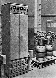
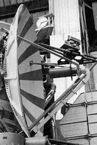
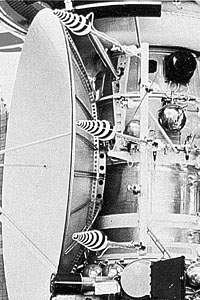
 A Pluton receiver
|
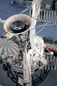
 Parametric Amplifier
|
|
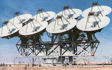
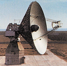
The system, code named Pluton, was located on the Crimean peninsula, northwest of Evpatoriia.
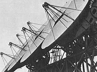
Three ADU-1000 antennas were built, each with 8 duralumin parabolic dishes 16 meters in diameter.
These were mounted on steerable frames constructed from battleship gun turrets and railway bridge trusses.
At site 1, two receiver antennas were built, and a few kilometers away at site 2, a transmitter was constructed.
The transmitter was modified for planetary radar experiments by installation of a low-noise receiver, which could be switched into its wave guide between pulse transmissions.
The transmitter is at 45°10′ N, 33°15′ E.
The meter and decimeter-band was received by a low-noise parametric amplifiers cooled with liquid nitrogen (note cryogenic tanks to the right of the equipment bay above). Sometime before 1962, liquid helium cooled MASER amplifiers were installed, increasing sensitivity six fold. Sometimes called a paramagnetic amplifier, it uses a ruby crystal in a strong magnetic field, doped with atoms of a paramagnetic element (e.g., chromium). It is tuned by varying the strength of the magnetic field, changing the spin-state transition energy. |
 The Pluton Transmitter
|
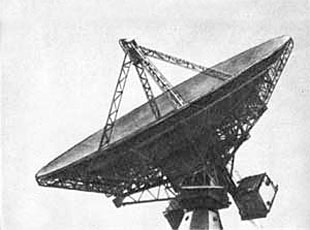 A Transmitter at Simferopol
|
|
In 1963, Lunar missions used a permanent station at Simferopol,
with a 32-meter TNA-400 parabolic antenna. It was capable of operating on the "meter", "decimeter" and "centimeter" bands. Lunar missions often used analog FM video and pulse-duration modulation, but planetary missions required digital signaling.
The Pluton transmitter was immensely powerful. Its initial 10 kW klystron amplifier was replaced by four amplifiers totalling 80 kW. In pulsed mode, for planetary radar, it emitted a radiant intensity of 250 megawatts per steradian. From a distance of 65 million kilometers, it could bounce 15 watts off the surface of Venus.
As an example, the 1966 Luna-9 camera sent 250 Hz analog video, frequency modulated on a 1500 Hz subcarrier tone, which was phase modulated on a carrier of 183.538 MHz. Scanning vertically at one stroke per second, this yields an equivalent Nyquist rate of 500 pixels per column, with 6000 columns making up a full cycloramic image. |
 An FSK Signal
|
 A PPM Signal
|
|
In 1962,
contact with Mars-1 was maintained to a record breaking distance
of 106 million km.
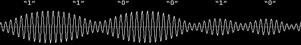
Telemetry was sent using digital FM, also called frequency shift keying (FSK).
Binary data, at up to 64 bits/sec, was represented by switching between an 1100 Hz and 1700 Hz subcarrier, which was phase modulated on the radio carrier wave.
A simulation can be heard
here.
Venera-2 and Venera-3 introduced the use of orthogonal codes for improved error correction.
Mars-1 image data was to be sent at 90 pixels/sec on 5-centimeter band using pulse position modulation (PPM), where time between pulses represents a quantity. The impulse transmitter used 50 watts average power, but the extremely short pulses were 25 kilowatts, which allowed a fairly high data rate. This scheme is particularly well suited to image data, because small errors lead to minor changes in gray level, instead of the "salt & pepper noise" of pulse-code modulation. A simulated signal can be heard here. A 20-watt, 200 pixel/sec PPM image telemetry system was designed for the Zond-2 Mars mission. Alternatively, it could transmit images on 8-centimeters with frequency shift keying, at 512, 1024, 2048 or 4096 bits/sec. In 1965, Zond-3 photographed the far side of the Moon and transmitted the results successfully at 2.2 million km and again at 31.5 million km. |
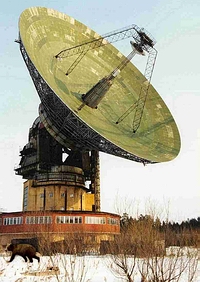
 P-400 Saturn Antenna (Evpatoriia)
|
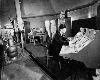 Saturn Station Control Room
|
|
During the mid and late 1960s, the Saturn-MS and Saturn-MSD systems were installed at
more than half a dozen sites. This included 25 and 32-meter "parabolic" antennas (P-200 and P-400),
MASER amplifiers cooled by liquid helium, and modernization of existing antennas.
The antennas have a Cassegrain design with a 4.3-meter secondary reflector at the prime focus (on the 25-meter version), and a broad-band corrugated horn at the final focus.
The actual shapes of the dish and secondary reflector are computer-optimized, to maximize antenna gain in the working range of wavelengths.
A PSK Signal At some point, probably beginning with Venera-9, the modulation scheme was changed from frequency shift keying to phase shift keying. In this system, binary zero and one are represented by 180° differences in phase. PSK is more energy efficient than FSK, because clearly discernable binary values are encoded in a narrow band around a single carrier frequency, and more cosmic background noise is thus tuned out. A simulated PSK signal on a 1000 Hz carrier can be heard here. This second generation system handled analog and digital telemetry. Convolution coding (K=6, R=1/2) and Viterbi decoding were introduced. Both FM and pulse-position modulation were used. It is unclear what combination of the new 32-meter dishes and the ADU-1000 Pluton antenna were used.
The Mars missions, M-69 (which was destroyed at launch) and Mars-2 to Mars-7 used several telemetry systems, including 1024 pixels/sec (about 6144 bits/sec) image transmission with PPM on the 5-centimeter band and science data at 128 bits/sec with continuous-wave FSK. Venera-9 returned the first images of the surface of Venus, using a digital FM system at 256 bits/sec on each of two camera channels. After the 1973 Mars missions, the use of pulse position modulation was discontinued. |
 Evpatoriia Dish (70m)
|
 Ussuriisk Dish (70m)
|
 Kaliazin Dish (64m)
|
|
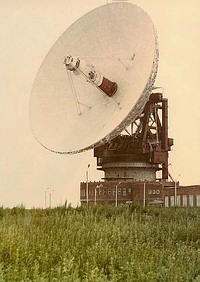
From 1973 to 1978, a 70-meter antenna was constructed
at the Western Center for Deep Space Communication in Evpatoriia, and in 1986 another at the
eastern center in Ussuriisk, Siberia.
The new antenna, called P-2500, was first used in the Venera-11 and Venera-12 mission to Venus.
In 1979, two 64-meter dishes were constructed near Moscow at Kaliazin and Bear Lake.
In 1988, Kvant-D, the third-generation telemetry-electronics system, used only frequency modulation on continuous carrier waves with rates from 512 to 131,000 bits/sec.
The Phobos and Mars-96 missions did (or would have) used Kvant.
Venera-11 to 14 used two channels of 3072 bits/sec each, for transmission of science data and digital color images. Images were sent at 10 bits per pixel (512 gray levels and a parity bit), 252 pixels per scanline, and 1.22 lines per second, which agrees with the reported data rate. This is the rate between the lander and orbiter, and also the data rate between orbiter and Earth when using the semi-directional antennas. Higher unreported rates were possible when the parabolic antenna was used, but this was done sparingly, to conserve attitude control gas. The telemetry system of the Vega mission was described in more detail. A high-data-rate channel (BRL) used the high-gain antenna and could send 65536 bits/sec, or half that rate if propogation conditions were poor. This was used for real-time transmission, and required the spacecraft to assume 3-axis stabilization with the parabolic antenna pointed toward Earth. Scientific data was sent on a low-data-rate channel (BTM) of 3072 bits/sec which used the helical semi-directional antennas. These operated during the normal spin-stabilized mode of flight, periodically dumping information stored on tape recorders. American Deep Space TelemetryPrior to the construction of the 64-meter Mars station at Goldstone, American missions were limited to 8.33 bits/sec. This meant that the 256×256-pixel images of Mars from Mariner-4 took weeks to transmit.64-meter antennas were built at Goldstone and in Spain and Australia, from 1966 to 1972. This permitted scientific data to be sent at 66.6 - 670 bits/sec and image data (with higher error rate) at 16,200 bits/sec on Mariner-9. Care should be taken when comparing these numbers with Soviet rates, because the commensurate error rates are not known. For Venus synthetic aperture radar data, one might compare the 100,000 bits/sec Venera-15 rate with Magellan's rate of 115,000 - 268,800 bits/sec six years later. Progress in error coding, antenna design and coherent ganging of multiple antennas has lead to a steady increase in data rates. In the early 1980s, the 64-meter dishes were enlarged to 70 meters. In 2004, the Cassini probe will be able to send 120,000 bits/sec from Saturn. By the late 1980s, America and the Soviet Union began to cooperate and interlink their deep space telemetry systems. Spacecraft Radio SystemsThe other end of the telemetry system is the spacecraft. Soviet spacecrafts used semi-directional receivers for telecommands. Telemetry transmission to Earth was accomplished with parabolic high-gain antennas. Antenna lock was acquired periodically, to download recorded science data during flight. Lock was maintained continuously during a planetary flyby, like Venera-11. FSK continuous-wave transmitters used 100 watt traveling wave tubes. PPM impulse transmitters were independent units operating at 50 watts average and 25,000 watts peak. |
 Directional
|
 Semi-Directional
|
 Meter-Band Semi
|
|
Starting with the 1M Mars probe in 1960, Soviet probes used a parabolic high-gain antenna (above left) to transmit scientific data to Earth.
Decimeter and centimeter-band transmitters (around 920 and 5800 MHz) shared the same dish.
Circular polarization was used, making the signal strength independent of the relative orientation of transmitter and receiver.
The spacecrafts had a special 3-axis orientation mode, locking onto the Sun and Earth, to aim the highly directional antenna.
During normal flight, Soviet spacecrafts assumed an uniaxial orientation (constant solar orientation) with the solar panels facing the Sun and a slow spin (six revolutions per hour) about that axis. Semi-directional conical spiral antennas (above center) were used to receive commands from Earth on 770 MHz. They were also used to send telemetry at slower bit rates. Attitude control gas and power was not expended on the parabolic antenna except when increased real-time bit rates were needed during a planetary encounter. Above right, large meter-band helical antennas can be seen on the backs of the solar panels. These were used for 186 MHz data links between spacecraft bus and descent vehicles. On Mars-3, the data link between lander and orbiter was 72,000 bits/sec, and data was recorded for later retransmission. On the Venus probes, 6144 bits/sec was used for real-time relayed data, from lander to bus to Earth (as well as recording and later replays). |
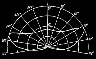
 Radiation Pattern from 60° Spiral
|
 Pattern from 50° Spiral
|
| Conical spiral antennas can generate a variety of radiation patterns. They may contain a single spiral, or two interleaved (bifilar) spirals 180° out of phase. The angle of the spiral determines radiation patterns ranging from a pear-shaped pattern that beams along the axis (above left) to a funnel-shaped pattern that concentrates radiation at a lower angle. |
 Venera-4 Antenna I
|
 Venera-4 Antenna II
|
| Two or three different conical antennas are typically seen on the spacecraft bus. During flight the spacecraft spun about the solar axis, with the conical antennas pointed toward the Sun. Their funnel-shaped radiation patterns were designed to remain focused on the Earth. During the course of the journey, the program timing unit would switch between different antennas, using the one with the best funnel angle. |
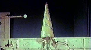
 Venera-7 Antenna
|
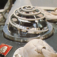
 Venera-8 Antenna
|
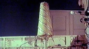
 Venera-9 Antenna
|
|
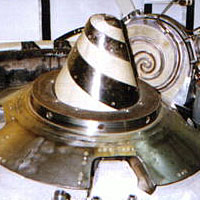
Early lunar and Venusian landing vehicles were designed to beam telemetry directly to the Earth. The Venera-7 antenna (above left) was designed to produce a pear-shaped radiation pattern. It landed in the center of the Venusian disk, where it was night and the Earth was directly above it.
Unfortunately, Venera-7 landed hard (about 35 mph) and came to rest on its side, causing the signal to drop to about 3 percent normal strength.
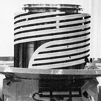
Venera-8 measured illumination levels, and had to land in the thin illuminated crescent visible from Earth. It's bifilar spiral antenna (above center) was shaped to produce a funnel-shaped radiation pattern, since its line of sight to the Earth was 30° above the horizon. From Venus, these probes used 1 bit/sec frequency modulation (FSK) on the decimeter band. Venera-9 (right) was designed to transmit images and telemetry to a relay spacecraft bus, sweeping across the sky overhead. The meter-band helical antenna transmitted two frequencies (one for each camera) and was quadrifilar, made up of four helical antennas 90° apart. Quadrifilar antennas can have adjustable radiation patterns, controlled by phase offset of the four elements. So this design may have been chosen to allow the radiation pattern to change as the relay bus moved from horizon to zenith to horizon. |
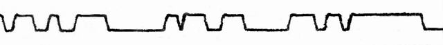 Plot of Signal from Venera-4 (1 bit/sec)
|
|
Various factors influence the rate at which information can be transmitted from a distant spacecraft.
Signals from Mars or Venus are attenuated by the great distances and degraded by random cosmic radio noise. Commands from the earth can be sent at high power, but solar-powered space probes cannot transmit a continuous carrier at multi-kilowatt power.
To be continued ... |
 A.F. Bogomolov
|
 V.A. Kotel'nikov
|
 M.S. Riazanskii
|
|
Acknowledgements Many image are from NASA and come courtesy of their generous non-commercial usage policy. In particular, many are from the web site of David R. Williams, National Space Science Data Center, nssdc.gsfc.nasa.gov. The photo of the Evpatoriia 70-meter antenna is courtesy of Team Encounter LLC. Special thanks to Viktor Kerzhanovich, Vladimir Kurt and Oleg Rzhiga for their recollections about radio equipment and planetary radar systems. |