|
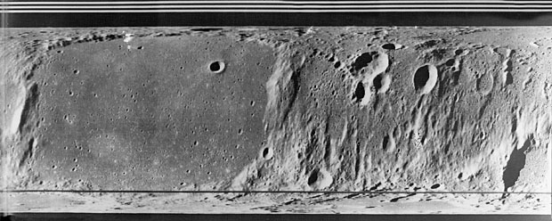
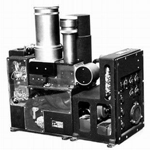
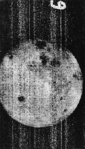
The 1965 Zond-3 mission returned 23 pictures (with orange filter) and an UV spectra of the far side of the Moon.
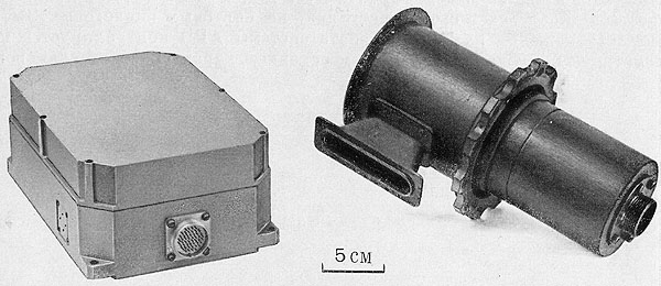
A 106.4 mm objective lens was used on this camera.
In addition, some test patterns were pre-exposed at the start and end of the film.
Images were taken and developed every 2.25 minutes, with alternating 1/100 and 1/300 second exposures.
A rapid 67 line/picture survey scan was first performed, and then commands were sent to rescan images at high resolution, with some resent several times.
It continued on to a distance equivalent to Mars fly-by, rewinding the film and testing image transmission several times.
As before, a 5-centimeter-band impulse transmitter sent pixel values to Earth, or alternatively, an 8-centimeter-band continuous wave transmitter could send the results. Most likely, both systems were tested at various distances.
In high-quality mode, images were sent at 550 pixels per second (2 seconds per scanline), requiring 34 minutes to send a 1100×110 image.
A 285-355 nm UV spectrograph was incorporated into the camera and recorded onto three frames of the film.
A second, coaxial, UV spectrometer measured 190-275 with a photomultiplier detector and output digital telemetry.
A coaxial 3-4 micron IR spectrometer was included on Mars missions, to investigate common organic molecular absorption bands, and a 6-40 micro IR spectrometer was included on Venus missions to investigate thermal balance. Spectrometers were designed by A.I. Lebedinskii and V.A. Krasnopol'skii.
Zond-2 may have carried two of these cameras with 200 and 500 mm lenses, but failed en route to Mars.
Luna-12 carried two cameras of this design (one with a 500 mm lens) in a low-altitude lunar orbit in 1966. Luna-12 returned 40 images per camera at a doubled scanning speed.
An identical mission on Luna-11 experienced a failure of its orientation system and photographed black space.
Venera-2 carried one camera with a 200 mm lens to Venus, but the spacecraft failed before its final planetary-encounter telemetry playback.
 M-69 Phototelevision Complex
|
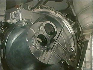 Pressurized Housing
|
|
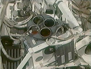
The M-69 orbiter, a 1969 Mars attempt, contained three cameras of more advanced design, with lenses of 35, 50 and 250 mm.
A wheel of glass filters (red, green, blue, clear) is used by one camera (or perhaps shared by two cameras) to take color photographs.
They each held 160 images on a specially designed film.
Upon arrival, the film was chemically activated, so it would not be exposed by cosmic radiation during the long flight.
Images were scanned at 1024×1024 resolution and transmitted by pulse position modulation on 6 GHz.
Unfortunately, the two M-69 probes were destroyed in launch failures of the new Proton rocket.
In 1971, Mars-2 and Mars-3 entered orbit. They each carried two phototelevision cameras with 52 mm and 350 mm objectives. Little telemetry was received from Mars-2, due to telemetry systems problems. Mars-3 performed well, but its centimeter-band impulse transmitter failed, and images were returned on the pulse-code-modulated decimeter band. Only 60 images were taken from December 1971 through March of 1972, some of which were transmitted, but only at a low 250-line resolution.
|
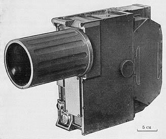 Mars-5 Camera "Zufar", 350 mm
|
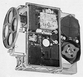 Mars-5 Camera "Vega", 52 mm
|
|
Mars-4 and Mars-5 orbiters carried the Mars-3 style phototelevision cameras on their 1973 mission. The operation was essentially the same as the Zond-3 camera, with various technical improvements in the optics of the film scanner, using a newer FEU-103 photomultiplier tube.
It held 480 frames on 20 meters of 25.4mm film, stored in a radiation-shielded magazine.
Exposure alternated between 1/50 and 1/150 second, with a thin calibration image between each frame. After development the film could be rewound and scanned at various rates, by telecommand. Ten scanning options were available.
In practice, images were all transmitted for preview at 235×220, nominal resolution was 940×880, and particularly interesting pictures were retransmitted at 1880×1760 pixels, the highest quality mode.
\
Transmission of images was carried out by a special purpose impulse transmitter and pulse position modulation. Rates of 512 or 1024 pixels per second could be selected.
1024 pixels/sec is sometimes given as "6144 bits/sec", assuming that 6 bits is approximately the information in an analog pixel value.
All other telemetry was sent by the regular onboard transmitter, as digital data on a phase modulated continuous carrier.
|
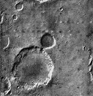 Image from Mars-5 (350 mm lens)
|
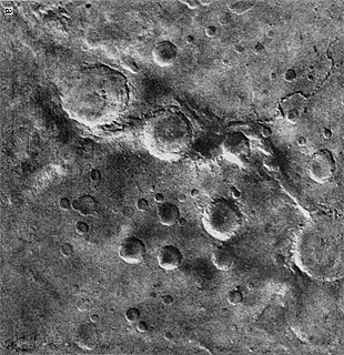 Image from Mars-5 (52 mm lens)
|
|
As on Mars-3, two cameras were installed on each spacecraft, one with a 350mm telescopic cassegrain lens with an orange longpass filter ("Zufar-2CA"), and the other with a 52mm lens and four color filters ("Vega-3MCA").
These weighed 9.2 and 8.5 kilograms, respectively.
The wide-angle camera could be operated with the red filter, the orange filter or a mode of sequentially shooting through red, green and blue.
Mars-4 returned 12 images during a fly-by, and Mars-5 returned 108 images in the course of its orbiting survey.
The American Lunar Orbiter missions (1966-1967) carried film cameras with automatic development and scanning. While the narrow-angle images were badly motion blurred, the wide angle images were the highest quality pictures taken of the Lunar surface up to that point.
Optical-Mechanical Cycloramic Cameras
Selivanov and Iuri M. Gektin designed landscape cameras for Moon, Mars and Venus landers.
Instead of panning a television camera, he decided to scan the scene with a pinpoint photometer.
This required a much simpler apparatus with some advantages.
A precise measurement of luminance was made at each pixel, and the entire landscape was returned as a single seamless image.
These cameras probably evolved from early cycloramic telephotometers by A.M. Kasatkin and others, used for low-resolution UV imaging and photometry from high altitude rockets.
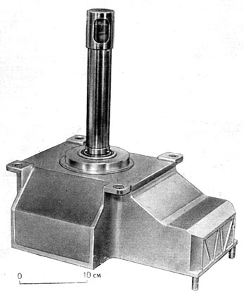
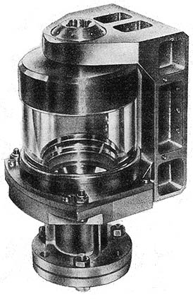
Luna-4 through Luna-8 contained a cycloramic optical-mechanical camera built by I.A. Rosselevich's team at the Leningrad Scientific Research Institute of Television. It was heavier and lower resolution than Selivanov's Luna-9 camera, and it operated inside a pressurized glass cylinder instead of being exposed to vacuum.
|
|
|
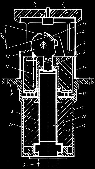
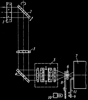
- 80 × 205 mm housing
- Mounting flange
- Electrical connector
- Cap
- Thin dacron window
- Pressure equalization valve
- Thermal insulation cover
- Support pipe
- Objective lens & diaphram
|
- FEU-54 photomultiplier tube
- Scanner motor
- Scanning mirror
- Shaped pushing-mirror cam
- Motor control electronics
- Electrical connection brushes
- Photomultiplier power supply
- Logarithmic pentode amplifier
|
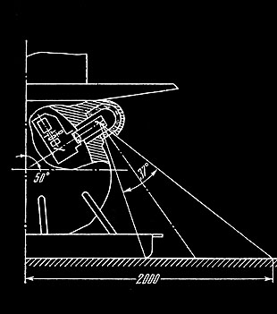
On the Luna-9 camera, seen above,
the objective lens was focused at the hyperfocal distance, returning a sharp image of terrain between 1.5 meters and the horizon.
Logarithmic photometry and automatic gain control (governed by a photocell) allowed the camera to operate with a wide range of luminance, from 80 to 150,000 lux.
Sensitivity could also be adjusted by telecommand.
The PMT and amplifer were the same as in the film scanner of the Zond-3 phototelevision camera.
Remarkably, while containing vacuum tubes, a motor and the 1700 volt power supply for the PMT, the camera weighed 1.3 kilograms and consumed only 2.5 watts.
The upper assembly with oscillating mirror and motor rotated freely in the metal sleeve, making electrical contact through brushes.
Scanning was vertical, with slow rotation to sweep out the horizontal image swath.
The finely built mechanical action of the mirror was precise to 1/3 pixel spacing.
A full 29° × 360° panorama of 6000 vertical lines could be returned in 100 minutes.
On command, the camera could scan forward, in reverse, or at 4× speed for quick survey or positioning.
A 250 Hz analog video signal was generated, which was frequency modulated on a 1.5 KHz subcarrier.
That in term was phase modulated onto the 183.538 MHz telemetry carrier.
250 cycles per line is theoretically equivalent to 500 pixels, which is how the resolution is often reported.
Lunar images were sent as analog video, because a strong communication channel could be established between the Moon and the 32-meter dish at Simferopol.
For later missions to Mars and Venus, the video signal was digital from camera to ground station.
|
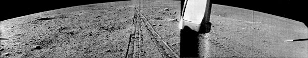
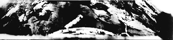
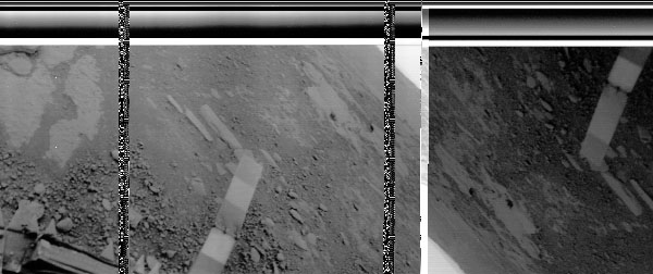
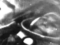
 Fragment of Luna-13 panorama
|
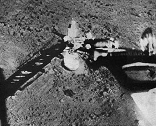 Full-resolution detail
|
|
The images above show part of the lunar landscape revealed by the Luna-13 camera. Pieces of the landing craft are seen in the distance on the left view.
On the right, a detail at original resolution shows the extended gamma-ray densitometer and a close view of the lunar soil.
These first landers relieved fears that the lunar surface might be composed of dust, into which spacecraft would sink.
It is important to remember that we can only see scans of printed images, many generations of duplication from the original electronic signal. Unless the magnetic tapes of the FM video signal are read and processed into modern digital images, we will not see the true quality of these images.
|
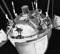 Luna-9 Lander
|
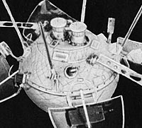 Luna-13 Lander
|
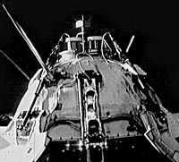 Mars-3 Lander
|
|
Luna-9 was the first spacecraft to land on the Moon, using an airbag landing system similar to the recent Mars Pathfinder. In 1966, it returned three panoramas. Its signals were also intercepted by the British radio telescope at Jodrell Bank, and a Manchester newspaper published the pictures before the Russian press.
Luna-13 returned five panoramas from another landing site, later that year.
Taken over several days, they show the surroundings under different angles of illumination (the Moon rotates 13° per day).
It had two cameras for redundancy or stereo, but one failed.
In 1971, Mars-3 was the first spacecraft to land on the red planet.
Two cycloramic cameras were installed, as on Luna-13.
Like the second generation lunar cameras, they had 500 × 6000 pixel resolution, and scanned at 4 lines per second.
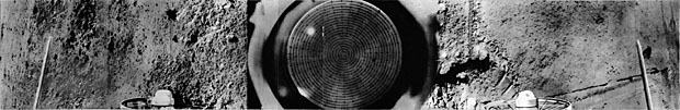
Pen Plotter Displays Signal from Mars-3 Lander
Unfortunately, contact with the lander was lost after only returning 15 to 20 seconds of video from each camera.
This fragmentary image of 79 scanlines has been reported to be featureless, despite extensive computer analysis by Soviet scientists.
The plotter, shown above in a Soviet documentary on Mars-3, is drawing the video signal in horizontal strokes. The image is often misinterpreted as a view of the Martian horizon, but the cycloramic camera was transmitting vertical strokes, just as the Luna-9 camera did.
Thus the image should be rotated 90°, and its interpretation is unclear.
America's first Mars landers, in 1976, adopted the Soviet style of cycloramic cameras, using a mechanically swept 512-pixel linear CCD.
|
 Luna-16 Cameras
|
 Lunokhod Cameras
|
|
The second generation lunar missions contained improved versions of the cycloramic cameras, scanning at 4 strokes/second, and using the more stable and sensitive FEU-96 photomultiplier tube.
Automatic gain control for these cameras, and later Venus/Mars cameras, used an electronic circuit that monitored the camera output. Gain adjustments were smoothed over 5 to 10 seconds.
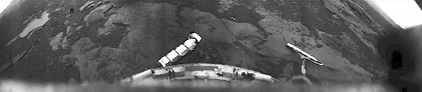
The sample-return missions, Luna-16 and 20 had a stereo pair of cameras focused on the drilling site to guide placement. Their resolution was 300×6000, and they were capable of viewing the sky and spacecraft. Luna-16 landed during Lunar night, illuminating the drilling area with lamps.
Panoramas from Lunokhod-1
The Lunokhod rovers (1970 and 1973) contained four cycloramic cameras (a pair on either side) for high quality imaging of the Lunar surface and sky.
Cameras scanning about an axis 15° from vertical covered a 180° panorama from 1.4 meters to the horizon.
Cameras scanning about an horizontal axis could cover a 360° view including the sky and stars, the ground beside the wheels, and a device to show precise rover level.
Generating 1000 Hz video signals, two cycloramic cameras could transmit at once, on subcarriers of 130 and 190 KHz.
The resolution of a 360° panorama was 500 × 6000, and hundreds of panoramas were returned by the rover missions.
For navigational purposes, two low-resolution vidicon cameras were mounted on the front of the rover, returning 250 lines of video at 10 frames per second.
|
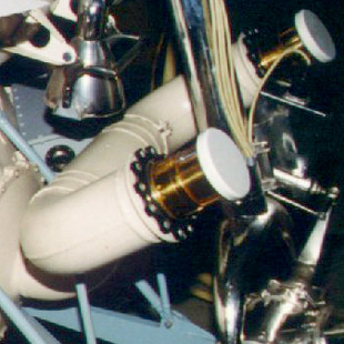
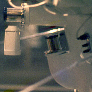
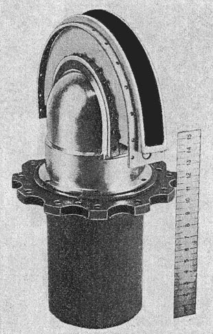
 Camera on Venera-9 Lander
|
 Quartz Pressure Window
|
|
Venera-9 and Venera-10 were the first probes to carry cameras to the surface of Venus, in 1975.
Conditions on Venus are extreme, pressures of almost 100 atmospheres and temperatures up to
475° C (890°: F).
To function in this hostile environment, several changes had to be made, although the basic design principals remained the same: a scanning mirror and a pinpoint photometer based on a photomultiplier tube.
The camera housing was mounted within the spherical pressure hull of the lander, and a periscope extension reached into a cylindrical pressure window.
The scanning mirror was moved by push wires, and was designed to operate at Venusian surface temperatures. The tube of the periscope was relatively nonconductive, and the camera housing was packed with a heat-absorbing phase-change material.
Forming a seal between the titanium frame and the quartz pressure window was particularly difficult, since differing thermal expansion takes place between outer space and the surface of Venus. Gold gaskets and specially shaped grooves solved this problem.
|
 Camera Schematic
|
 Placement of Camera
|
- 10 mm quartz window
- Scanning Mirror
- Compensating Lens
- Fixed Mirror
- 28 mm Objective Lens
- Image-Plane Aperture
|
- Photomultiplier Tube (FEU-114)
- Shutter
- Photosensitive Diode
- Stablized Lamp
- Light Guide
|
The compensating lens (3) was an elegant feature, designed to cancel out the refractive effect of the thick quartz pressure window.
Focusing at the hyperfocal distance yielded a depth of field from 0.8 meters to infinity.
The camera was programmed to scan forwards and backwards until the lander ceased to function.
During the return stroke, a calibration signal from a stabilized lamp was admitted to the photometer.
Two cameras were mounted symmetrically on a lander, angled to view both the immediate foreground and the horizon, in a single 180° panorama.
The 128×512 resolution was scanned at one line every 3.5 seconds, much smaller and slower than the lunar cameras. This was dictated by the telemetry rate (256 bits/sec) and the estimated minimum lander lifetime of 30 minutes. Note that 13 pixels of each line was a calibration pattern sent during retrace, and 115 pixels were video image data.
Contact was actually maintained for 50 to 60 minutes, and almost two complete panoramas were returned by both missions. Only one camera functioned on each lander.
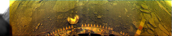
Venera-10 Panorama
The output of the photomultiplier and logarithmic amplifier was digitized to 6 bits/pixel, with a seventh parity bit. All radio transmission from the lander to the orbiter was digital.
More information about these missions and spacecraft can be found
here.
The Venera-9 panorama can be viewed in a full-size format
here.
Degraded Publication of Venera-10 Panorama
Soviet space images are sometimes printed in astonishingly degraded forms. This is partially the result of generation loss, and partly an effect of cold-war-era propaganda.
Sometimes the only available glimpse of a device or an image from space is a photocopy from a Russian journal.
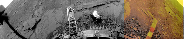
Venera-13, Short Program (Camera I)
Venera-13, Complete Program (Camera II)
Venera-13 and Venera-14 landed on Venus in 1982, returning higher resolution images in color.
Bandwidth between lander and the fly-by relay spacecraft was increased by a factor of 12, allowing 252×1024 pixel images to transmitted at one line per 0.82 seconds.
41 pixels per line comprised a retrace pattern, including the scanning of a stabilized light source through a photometric wedge.
The basic design was very similar to the Venera-9 camera, but with many improvements.
The low noise of the photomultiplier tube gave a signal-to-noise ratio of 1000, allowing the video to be digitized at 9 bits per pixel. A 10th bit was added with parity.
Each lander had two cameras, which repeatedly executed programs of scanning and color filter changes.
One camera executed a "short program", beginning with a 180° scan through the clear filter, then scanning back and forth for 60° with red/green/blue filters, and finally a 120° clear image as it reversed back to its starting position.
This would ensure a complete panorama and a full color section, even if the lander only survived for 30 minutes.
The second camera executed a "long program", scanning a full 180° with clear, red, green and blue filters.
They survived about two hours, and returned multiple panoramas.
|
 Enamel colors
|
 At 500° C and 100 atm
|
 Illuminated by Sky
|
|
The deployed color-calibration panels consisted of blue, green, red and gray sections of polysiloxane enamel and metal-oxide pigment.
Their color is depicted above, sRGB values calculated from measured spectra.
The enamels were tested and spectrographed under simulated temperature and pressure to measure the thermochromic and piezochromic color shifts.
The overall orange illumination seen in the color panoramas is due to Rayleigh scattering and possibly an unknown blue-absorbing chemical in the lower atmosphere.
The zenith sky spectrum was accurately measured by the lander, and its illumination of the heated, pressurized enamel spectra can be calculated.
The calculated colors do not exactly match the panels in the color panoramas.
The overall illumination is not only from the zenith color, although that should give the most contribution. The panels could be slightly covered with dust, and although they are made from highly resistant material, they could have been effected by atmospheric chemicals.
However, the largest effect is simply that the images from Venera-13 and 14 have never actually been properly color balanced, nor has the radiometric response function of the camera been established.
We do not yet know the precise colors of Venus.
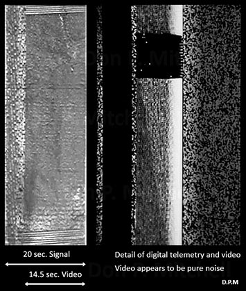
Section of Raw Venera-13 Digital Video
Venera cameras transmitted one continuous digital video signal, without break.
The two vertical bars of "static" seen above are interruptions to transmit telemetry from other onboard experiments.
The horizontal bars running across the top are the video front porch and a calibration signal fed into the photometer from an optical-density ramp and a stabilized light source.
Starting from the left, the scanner is working though a clear filter with automatic gain control (note variations in the brightness of the calibration).
The narrow band of very bright scanlines indicates that a high constant-gain setting has been switched on by the program control. The direction of the scanning also reversed at that point.
A few scan lines later, the red filter has dropped into position, and the image becomes darker.
|
Optical-Mechanical Linear Cameras
Conventional cameras focus an image onto a 2-dimensional image sensor. One problem with this is the limitation of resolution imposed by image sensor technology. It is easier to build a 1-dimensional camera and allow the orbital motion of the spacecraft to sweep it across the planet.
An innovation often attributed to Landsat-1, Soviet scientists first deployed linear cameras a year earlier, on Luna-19.
Built by Arnold Selivanov and Iuri Gektin, they represent an evolution of the panoramic camera used on Luna-9 in 1966.
|
 Luna-19 and Luna-22 Camera
|
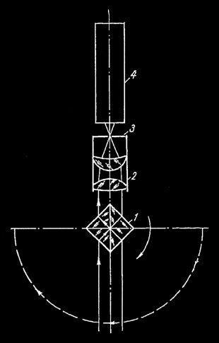 Schematic
|
|
These cameras, for 1971 and 1974 low-orbit survey, were designed to produce long, high-quality panoramas of the lunar surface.
They used a photomultiplier tube (4) as the detector, with a spinning prism to scan a 180° "cylindrical fisheye" image. The scan rate was 4 lines per second.
From an altitude of 100 kilometers, the craft could resolve 100 meters along the direction of scanning, and 400 meters along the perpendicular direction of flight.
The images extend to the lunar horizon, which was used to help calculate the precise orbital motion of the satellite
Fragment of a Luna-22 Panorama
The Luna-19 and Luna-22 "heavy orbiters" are still somewhat mysterious missions, although one objective was the mapping of the Moon's uneven gravitational field.
Luna-22 adjusted its orbit until it was skimming the lunar surface at 15 to 30 kilometers distance.
By one report, Luna-19 returned 5 panoramas and Luna-22 returned 10.
|
 Camera System on Venera-9/10 and Mars-4/5 Orbiters
|
|
The Mars-4, Mars-5 and Venera-9 orbiters contained linear cameras designed by Gektin and his team. They scanned images 30° wide and arbitrarily long, as the orbit of the spacecraft swept across the planet.
The camera design was similar to the cycloramic camera on Luna-9, but its scanning mirror oscillated without the need of a rotating assembly, using the satellite's orbital motion to sweep out an image swath.
It used automatic gain control and operated in a logarithmic-photometer mode.
Each scanline included some black and white calibration stripes transmitted during the return stroke.
The box, above left, is an analog 4-track tape-loop recording device designed to work with this linear camera.
It recorded up to 45 minutes of two 1000 Hz video signals as well as two synchronization signals from the onboard crystal oscillator.
Both cameras could be simultaneously recorded for 45 minutes, or one camera could record for 90 minutes.
The video could be read and digitized for transmission to Earth, at two speeds (i.e., at two pixels/line resolution).
Reports claim the tape recorder was also used to store the video signal from the lander, although technical papers stress that the radio signal from the Venera and Mars landers to the orbiter was digital, not analog.
|
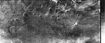 Mars-5 Linear Camera Image (Orange Filter)
|
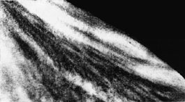 Venera-9 Image (UV Filter)
|
|
The Mars cameras used two photomultiplier tubes and returned images in three wavelength ranges. A PMT-112 (AgOCs cathode) with a red glass long-pass filter was used to image in infrared. A PMT-114 (multialkali cathode, also used on Venera lander) was used with red and orange glass filters to image those colors.
The cameras scanned at 4 lines/second, generating 1000 Hz video (250 cycles/line), which was recorded on magnetic tape.
The primary readout rate was 1 line/second, transmitted to Earth probably at 256 or 512 pixels/line. The option existed to scan at 4 lines/second and send reduced resolution at higher speed.
Mars-4 returned 2 panoramas, and Mars-5 returned 5 panoramas.
The Venus cameras both used the PMT-114 with violet and ultraviolet filters to obtain images in those spectral ranges.
It scanned at 2 lines/second, generating 1000 Hz video (500 cycles/line).
During transmission to Earth, the tape could be read and transmitted at 256 pixels/line in the primary mode, or at a slower special rate of 512 pixels/line.
Venera-9 performed 17 survey missions from October 26 to December 25, 1975, using the ultraviolet camera with the violet camera sometimes recording simultaneously. Resolution was 6.5 to 30 km, depending on the spacecraft altitude.
The panoramas, recorded over 30 to 50 minutes, were probably about 256 × 6000 × 6-bits in size, and contained highly elongated images of the planet.
They were contrast enhanced and linearly compressed by scanline averaging, to reduce noise and geometric distortion.
These images were higher resolution than the later Pioneer Venus cloud photometer, but unfortunately the images from this survey have never been released to the public.
The poor-quality images above are scanned photocopies of printed pictures.
Fobos-2 Thermal Image of Mars
In 1988, the Soviet Union launched Fobos-1 and -2, Mars orbiters with small vehicles intended to land on Phobos.
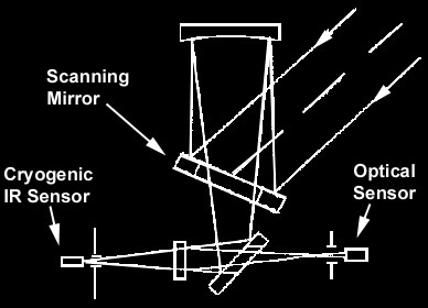
Selivanov and Gektin's team designed a 28 kilogram optico-mechanical camera, similar in basic design to the Mars-5/Venera-9 linear cameras.
Called TERMOSKAN, the camera contained two detectors:
One for 600-950 nm returned images in the red and near-infrared range.
The other, cooled by liquid nitrogen, imaged the thermal infrared wavelengths from 8.5 to 12 μm.
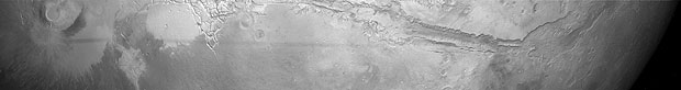
Seen above is the third of four scans around the equator of Mars, 512×3100 pixels, from Olympus Mons to the Valles Marineris.
The spacecraft was 3-axis stabilized, with the TERMOSKAN camera pointed away from the Sun.
A moving mirror scanned one dimension at 512 pixels/line and 1 line/second. The nearly circular orbit of the spacecraft moved the camera in a swath across the illuminated face of the planet.
The faint horizontal streak is the shadow of Phobos, following the spacecraft's orbit.
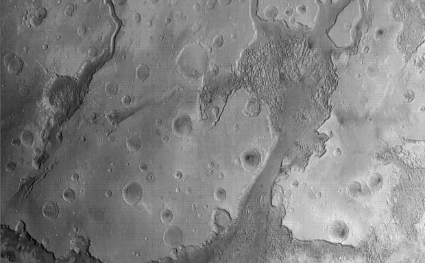
Full Size Detail of Thermal Imaging
Above is a full sized section from the second scan in the far infrared.
With 1.8 km resolution, the Fobos-2 images are several times higher resolution than the recent thermal IR images from Mars Global Surveyor.
Each scan line consists of 384 pixels of image and 128 pixels of calibration data (which has been omitted).
A later version of the camera was installed on Mars-96, which was destroyed in a launch mishap.
|
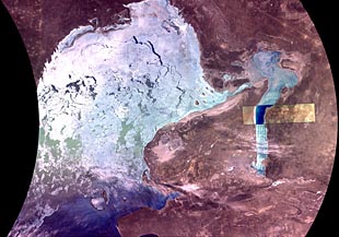 Image from MSU-SK
|
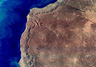 Image from MSU-E
|
|
Linear optical-mechanical cameras have been applied to non-military Earth observation satellites. In the early 1970s, two scanners were developed by Selivanov's team, for the Meteor weather satellites: MSU-M scanned 4 lines/sec by oscillating mirror (similar to the Mars-5 camera). It swept a 3000 km swath at four bands in the visible and infrared. MSU-S scanned 48 lines/sec by spinning prism (similar to the Luna-19 camera). It swept out a 2000 km swath with 240 meter resolution, in two spectral bands.
The two images above show images gathered from MIR in the 1990s.
The latest spinning-prism scanner, the MSU-SK, has been installed on Meteor-3M, Okean and Resurs-O satellites, as well as the MIR space station. It sweeps out a 600 km wide swath with an arc-shaped scan, returning up to 4756 pixels/line.
It is combined with the MSU-E push-broom camera, which uses three 2048-element linear CCD sensors. The MSU-E returns 200 lines/sec in a 45 - 78 km swath, running down the center of the MSU-SK image. A 24-bit image is returned, consisting of three channels selected from the set of 5 spectral bands on the MSU-SK and 3 bands on MSU-E.
Returned-Film Camera Systems
The highest quality images of the Earth and Moon have come from returned film, taken automatically or by astronauts. In America, the civilian space program was forbidden to develop automatic returned-film camera systems, a matter of some dispute during the planning of Landsat.
In the Soviet Union, the division between military and civilian space programs was less distinct. With high resolution returned-film imagery from Resurs-F available for topographic and Earth-resource applications, Soviet linear-scanning satellites like Resurs-O were designed for wider coverage than Landsat.
|
 Zenit Satellite
|
 Zenit-8 Return Capsule
|
 Resurs-F1 Capsule
|
|
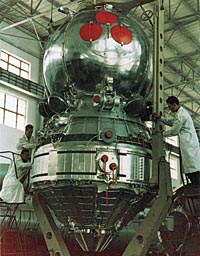
The world's first surveillance satellite was the Zenit-2, developed concurrently with the Vostok manned missions, and using the same spacecraft.
Since 1961, over 700 Zenit or Resurs-F satellites have flown, carrying a variety of camera systems and returning them in the spherical landing capsule.
The original Ftor-2 camera system, consisting of a 200 mm and 1000 mm camera, was designed by Iu.V. Riabushkin.
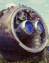
The Zenit-8 capsule above shows two telescopic KFA-3000 cameras, with a folded 3000 mm focal length. It probably held about 1800 frames of film, each 30 × 30 cm, yielding 2-3 meter resolution.
The camera systems were used an average of three times, before worn out by repeated launching and reentry.
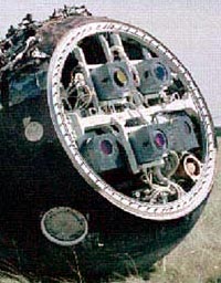
The Resurs-F1 capsule above shows five cameras. Two KFA-1000 cameras shot 30 × 30 frames of b/w or spectrozonal film through 1000 mm objectives (4-6 meter resolution).
Three KATE-200 cameras shot 18 × 18 cm color film through 200 mm objectives (15-30 meter resolution).
Spectrozonal film recorded 570-680 nm and 680-810 nm wavelengths in separate emulsion layers.
|
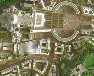 Rome from Resurs-F1
|
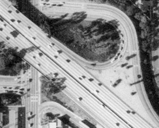 Los Angelas from Resurs-DK
|
|
Examples of Soviet returned-film imagery are impressive. The Resurs-DK camera has a resolution of 1 meter.
Russian companies now sell returned-film imagery from regions outside their national boundaries.
|
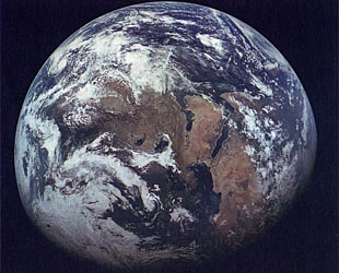 Zond-7 Image
|
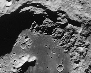 Zond-8 Image
|
Copyright © 2003,2004 Don P. Mitchell. All rights reserved.
|
 Iu.A. Gagarin on Vostok-1
 V.V. Tereshkova on Vostok-6
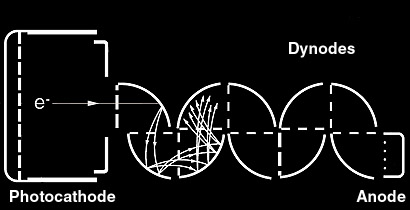 Front-End Photomultiplier Tube
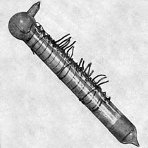 The First Photomultiplier Tube
 Luna-3 Camera ("Enisei")
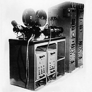 Receiving/Recording System
 Luna-3 Frame 28
 Frame 29
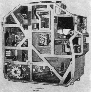 Mars-1 Camera
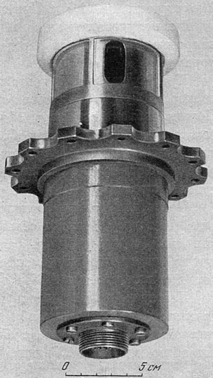
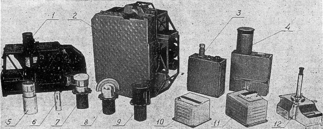
 Zond-3 Camera
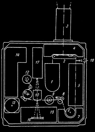 Diagram
 Far Side of Moon from Zond-3
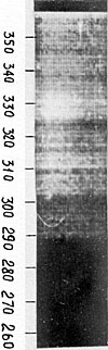 UV Spectrum
 P.F. Bratslavets
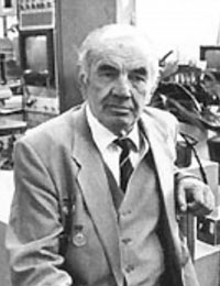
 A.S. Selivanov
 Iu.M. Gektin